+86-13349293098


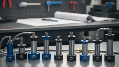
Choosing the right Outrigger Cylinder can determine whether a crane stands steadily or develops dangerous instability during lifting. This component transfers load from the crane frame to the ground through extended outriggers, hydraulic pressure, and support pads. Its performance affects leveling accuracy, lifting capacity, and operator confidence.
A suitable cylinder must match the crane’s rated load, operating pressure, stroke length, mounting dimensions, and retraction speed. Small differences matter. A few millimeters of misalignment can damage seals or create uneven extension. In wet yards, exposed rods may collect grit, causing scoring during retraction. On uneven construction sites, an undersized cylinder may struggle to maintain pressure after repeated lifts.
Experienced technicians usually compare the original specification with current working conditions. They inspect rod straightness, leakage, pin wear, hose routing, and pressure stability. Manufacturer data remains essential, but field evidence should not be ignored. Service records often reveal problems that a catalog cannot show. A cylinder may fit perfectly and still perform poorly under heat, vibration, or frequent side loading.
Safety comes before convenience. The selected unit should support documented load requirements and align with the crane manufacturer’s recommendations. It should also use compatible seals, hydraulic fluid, fittings, and protective coatings. Certification and inspection requirements may vary by region, so qualified professionals should verify them before installation.
A simple size comparison can mislead. That assumption deserves testing. The best choice balances strength, reliability, maintainability, and total operating cost. This guide examines those factors closely, while recognizing that real machines rarely work in perfect conditions. Proper selection is not merely a purchasing decision. It is a practical investment in controlled lifting, longer service life, and safer daily operations.
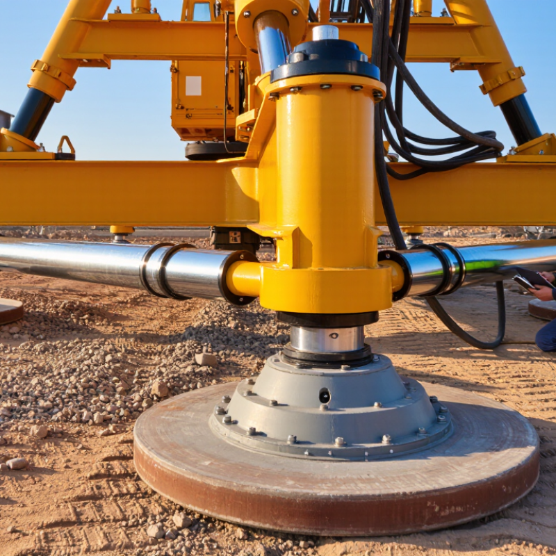
An outrigger cylinder does more than extend a crane’s support leg. It transfers load from the frame to the ground through controlled hydraulic movement. During setup, the cylinder positions each outrigger and helps maintain a level working platform. A small mismatch in extension can shift pressure toward one corner. That shift may reduce the crane’s safety margin. In practical inspections, uneven pads, soft soil, and trapped air often create trouble before lifting begins. Stability starts at ground contact.
The cylinder must resist compression, side loads, vibration, and repeated cycles without unwanted drift. Its rod, seals, pin joints, and hydraulic connections deserve close attention. A worn seal may cause slow retraction, while a bent rod can increase friction and uneven loading. Operators should check oil leaks, damaged chrome surfaces, loose pins, and unusual movement. Pressure readings can support diagnosis, but they cannot replace visual inspection or firm ground assessment. Follow the crane’s approved load chart and setup procedure every time. Smooth extension does not prove full stability.
Choosing the right cylinder means matching rated force, stroke length, mounting geometry, and operating environment. Salt, dust, low temperatures, and frequent transport can change maintenance needs. A correctly sized cylinder can still perform poorly when pads are undersized or the ground settles. It is easy to trust equipment that looks normal. That assumption needs questioning. Record extension positions, inspect after heavy lifts, and replace questionable components with verified parts. Small details matter.
Choosing an outrigger cylinder requires more than matching its outside dimensions. Bore, stroke, pressure, and force must work together. The bore determines piston area and affects the cylinder’s lifting capacity. A larger bore usually produces more force, but it may also increase weight and oil demand. Stroke controls how far the outrigger can extend or retract. Too little stroke can leave the crane unstable on uneven ground.
The bore determines piston area and affects the cylinder’s lifting capacity.
Working pressure must remain within the cylinder, hose, valve, and crane system ratings. Force is calculated with F = p × A, where A equals π × bore diameter² ÷ 4.
For example, a 100 mm bore has an area near 7,854 mm². At 20 MPa, its theoretical force is about 157 kN. Actual output will be lower. Friction, pressure losses, rod size, and seal condition all matter. This is where specifications can look precise but still mislead.
Tips:
Check bore and stroke against the manufacturer’s load data, not appearance alone. Confirm pressure in compatible units. Inspect the rod for scoring, and measure extension under a controlled load.
A practical mistake is ignoring retraction force. The rod reduces effective area, so pushing and pulling capacities differ.
I have found that small measurement errors can change the result significantly. Recheck calculations before installation. Safety depends on details.
Choosing an outrigger cylinder starts with more than its rated tonnage. Under EN 13000, crane capacity depends on load moment, working radius, boom angle, and ground reactions. ISO 4305 assesses stability by comparing overturning moments with stabilizing moments. A cylinder that lifts the beam is not automatically a cylinder that protects the crane.
A practical check uses real figures. An 80-ton load at an 8-meter radius creates about 640 tonne-metres of load moment, before dynamic effects. Uneven ground can increase one outrigger reaction sharply. The selected cylinder should therefore match rated force, stroke, locking reliability, and allowable pressure. I have seen capacity charts look safe while a soft shoulder quietly changes the calculation. Small details matter.
HSE recorded 138 worker fatalities in Great Britain during 2023/24, although its report does not isolate outrigger failures. The number still supports conservative lifting controls. Field teams should verify cylinder force against the manufacturer’s pressure data, then confirm bearing pressure and chassis level. A 2-degree lean can change the load path. That is uncomfortable, but realistic. EN 13000 documentation, ISO 4305 stability checks, and site-specific ground data should agree before lifting begins. A perfect calculation can still fail when the pad sinks.
Pressure rating is not lifting capacity. A cylinder produces force through F = P × A. With a 100 mm bore, 210 bar delivers roughly 165 kN. At 250 bar, output reaches about 196 kN. At 350 bar, it approaches 275 kN before losses.
These calculations show the attraction of higher pressure, but real output falls with seal friction, oil temperature, valve losses, and imperfect maintenance.
ISO 4413:2010 requires hydraulic systems to control pressure safely and prevent unexpected movement. EN 13000:2010+A1:2014 also connects crane stability with load cases, support conditions, and system design. Pressure alone cannot prove that an outrigger is suitable. A 350-bar cylinder may require stronger hoses, fittings, welds, pins, and mounting brackets. It can also increase stored energy during a failure. The 2023 Global Mobile Crane Market Report identifies infrastructure projects as a major demand driver, making reliable setup equipment increasingly important.
A practical mistake is treating 350 bar as automatically better. It may be excessive for a compact crane. A 210-bar system can provide dependable performance when its bore and safety factors match the load. The 250-bar option often offers a useful balance between force and component stress. Field inspections should check rod scoring, slow retraction, hose abrasion, and uneven ground contact. I would not specify pressure from a catalogue figure alone. The calculation looks clean. The jobsite rarely does.
Why Choose the Right Outrigger Cylinder for Cranes?
A suitable outrigger cylinder must support stability before lifting begins. Its safety features deserve close attention. A pilot-operated check valve can help hold the cylinder during hose failure. A pressure relief valve limits excessive hydraulic force. Hose-burst protection adds another layer when a line is damaged. Mechanical travel locks are valuable during transport and maintenance. They should not replace sound hydraulic design.
Inspection should begin with the cylinder rod, seals, mounting pins, and weld areas. Look for pitting, scoring, oil marks, bent rods, and loose connections. Check whether the outrigger settles under a steady load. Even slight drift can change the crane’s footprint. Measure operating pressure against approved specifications. Inspect hoses for abrasion, cracking, twisting, and heat damage. Keep clear records, including photographs and abnormal noise observations. Small details often reveal larger alignment problems.
ISO 4413 provides general safety requirements for hydraulic fluid power systems. It covers risk reduction, component selection, pressure control, piping, maintenance, and clear documentation. However, ISO 4413 compliance alone does not certify an entire crane. The complete machine still needs applicable crane standards and a documented risk assessment. Installation should be reviewed by competent personnel. A clean checklist can still miss poor ground conditions or incorrect outrigger placement. That is why inspection results should be questioned, not merely filed. A cylinder may appear strong, yet its mounting angle can quietly reduce stability.
| Evaluation Dimension | Recommended Specification or Feature | Inspection Criteria | Typical Acceptance Requirement | Safety Importance | ISO 4413 Relevance |
|---|---|---|---|---|---|
| Cylinder Function | Single-acting or double-acting hydraulic outrigger cylinder selected according to the crane design, deployment sequence, and required load-holding method. | Confirm the cylinder type matches the hydraulic circuit diagram and the crane manufacturer’s operating procedure. | Correct movement, extension, retraction, and synchronization with the outrigger control system. | Critical | ISO 4413 requires hydraulic systems to be designed and installed so that intended functions can be performed safely. |
| Rated Working Pressure | Maximum allowable working pressure must be equal to or greater than the hydraulic system’s specified maximum working pressure, including applicable pressure peaks. | Compare the cylinder nameplate and technical documentation with the crane hydraulic schematic and measured relief-valve setting. | Rated pressure is not lower than the system’s maximum permissible pressure; no pressure excursions beyond the design limit. | Critical | ISO 4413 emphasizes component suitability, protection against excessive pressure, and safe energy control. |
| Load-Holding Protection | Pilot-operated check valves, hose-rupture protection, or an equivalent load-holding arrangement located as close as practicable to the cylinder. | Inspect valve installation, hose connections, leakage, contamination, and correct pilot operation. Perform a controlled holding test. | Outrigger position remains stable when controls are neutral and when hydraulic supply is interrupted, subject to the crane’s approved test procedure. | Critical | ISO 4413 addresses prevention of unexpected movement and the need to control stored hydraulic energy. |
| Mechanical Locking | Positive mechanical retaining or locking devices should be provided where required by the crane design, especially for transport or long-duration support. | Check pins, latches, locks, retaining clips, and locking indicators for deformation, wear, corrosion, and full engagement. | Locking device is complete, secure, visible, and capable of preventing unintended retraction or displacement. | Critical | ISO 4413 supports the use of measures that prevent unintended movement; mechanical locking may be necessary where hydraulic pressure alone is insufficient. |
| Rod and Barrel Strength | Rod, tube, base connection, clevis, and mounting structure must be designed for axial loads, side loads, buckling risk, and the crane’s outrigger geometry. | Check for bending, dents, scoring, cracks, distorted mounting holes, loose fasteners, and evidence of side loading. | No visible deformation, cracking, abnormal wear, or mounting looseness; cylinder alignment remains within the approved design condition. | Critical | ISO 4413 requires components and assemblies to be selected and installed for the expected loads and operating conditions. |
| Corrosion Protection | Suitable rod coating, wiper seal, protective boot, drainage arrangement, and corrosion-resistant hardware for the operating environment. | Inspect exposed rod surfaces, welds, mounting points, fasteners, and areas exposed to salt, mud, chemicals, or standing water. | No pitting, flaking, deep rust, or corrosion that could damage seals or reduce structural integrity. | High | ISO 4413 requires environmental conditions and component protection to be considered during system design and maintenance. |
| Seal and Wiper Condition | Seals and wipers must be compatible with the hydraulic fluid, temperature range, pressure, speed, and contamination level. | Look for external oil leakage, wet rod surfaces, seal extrusion, damaged wipers, and repeated pressure loss. | No active leakage, seal displacement, or contamination ingress; leakage remains within the component manufacturer’s documented limit. | High | ISO 4413 requires prevention of hazards caused by leakage, contamination, and deterioration of hydraulic components. |
| Hydraulic Hose and Fittings | Hoses and fittings must be rated for the system pressure, compatible with the fluid, correctly routed, and protected from abrasion, crushing, heat, and sharp edges. | Inspect hose covers, bend radius, clamps, fittings, abrasion points, leakage, and date or condition markings where applicable. | No exposed reinforcement, severe abrasion, kinking, bulging, damaged fittings, or hose routing that can cause unexpected movement. | Critical | ISO 4413 includes requirements related to hose selection, installation, protection, and prevention of dangerous hose failure. |
| Pressure Relief and Control | A correctly adjusted pressure-limiting device must protect the cylinder and circuit from excessive pressure without defeating the required lifting or support function. | Verify relief-valve setting using calibrated test equipment and compare results with the approved hydraulic documentation. | Measured setting is within the documented tolerance and does not exceed the lowest-rated component in the protected circuit. | Critical | Pressure limitation and protection against overpressure are fundamental ISO 4413 design principles. |
| Pressure Loss and Drift | The cylinder and load-holding circuit should maintain outrigger position without unacceptable drift during normal support conditions. | Extend the outrigger, isolate the control, record position and pressure, and repeat according to the crane’s approved inspection procedure. | No movement beyond the limit specified by the crane manufacturer or applicable regulatory inspection procedure. | Critical | ISO 4413 requires prevention of unintended movement and safe behavior when energy supply or control signals change. |
| Position Indication | Visual indicators, limit switches, proximity sensors, or control-system feedback should clearly show whether the outrigger is stowed, extended, and properly positioned. | Operate each indicator and verify the signal at the operator control station; inspect damaged cables, sensors, and brackets. | Indication agrees with the actual outrigger position and prevents operation when the required deployment condition is not met. | High | ISO 4413 supports clear information, control, and safeguarding against incorrect or unexpected operation. |
| Structural Foot and Ground Interface | Footpad, ball joint, swivel connection, and retaining hardware must suit the permitted ground-bearing conditions and outrigger load. | Inspect footpad flatness, cracks, pin wear, joint freedom, retaining hardware, and contact with the ground or support mat. | Foot is secure, undamaged, correctly aligned, and fully supported without unstable contact or excessive point loading. | Critical | ISO 4413 covers safe integration of hydraulic actuators with mechanical structures; ground stability also requires crane-specific assessment. |
| Cleanliness and Hydraulic Fluid | Hydraulic fluid cleanliness, filtration, and maintenance should comply with the cylinder and hydraulic-system documentation. | Check reservoir condition, filter indicators, fluid appearance, water contamination, particle contamination, and maintenance records. | Fluid and filtration meet the documented cleanliness and service requirements; no contamination-related sticking or abnormal wear. | High | ISO 4413 requires consideration of contamination control, maintenance, and reliable operation of hydraulic components. |
| Functional Test | Test extension, retraction, holding, emergency stop behavior, interlocks, and response to loss of hydraulic power under controlled conditions. | Perform a documented no-load and operational test using the crane’s approved procedure and safe exclusion zone. | All functions operate smoothly without abnormal noise, jerking, leakage, uncontrolled movement, or alarm failure. | Critical | ISO 4413 requires verification of safety-related functions and control measures before operation and after relevant maintenance. |
| Inspection Frequency | Daily pre-use checks, periodic competent-person inspections, and detailed examinations should follow legal requirements, site rules, and the crane manufacturer’s instructions. | Review inspection records, defect reports, repairs, replacement history, and outstanding safety actions. | Inspection intervals are documented; defects are assessed and corrected before the crane is returned to service. | High | ISO 4413 requires maintenance information and inspection provisions, but it does not prescribe one universal crane inspection interval. |
| Documentation and Traceability | Maintain cylinder specifications, hydraulic schematics, pressure settings, inspection results, seal-kit information, repair records, and risk-assessment references. | Confirm documents are current, identifiable, available to authorized personnel, and consistent with the installed cylinder. | Complete, controlled documentation supports safe operation, maintenance, troubleshooting, and replacement selection. | Standard | ISO 4413 emphasizes information for use, maintenance instructions, warnings, and identification of components and safety functions. |
| Replacement Selection | Replacement cylinder must match bore, stroke, closed length, mounting dimensions, port configuration, pressure rating, seal material, and load-holding arrangement. | Compare the replacement against the approved drawing, parts list, hydraulic schematic, and physical installation dimensions. | No substitution is made solely on bore or stroke; all mechanical, hydraulic, environmental, and safety parameters are compatible. | Critical | ISO 4413 requires component compatibility and safe system integration; a replacement may require a documented design review. |