 +86-13349293098
Leave Your Message
-
Contact Phone
-
 Contact WhatsApp
-
 Contact Email
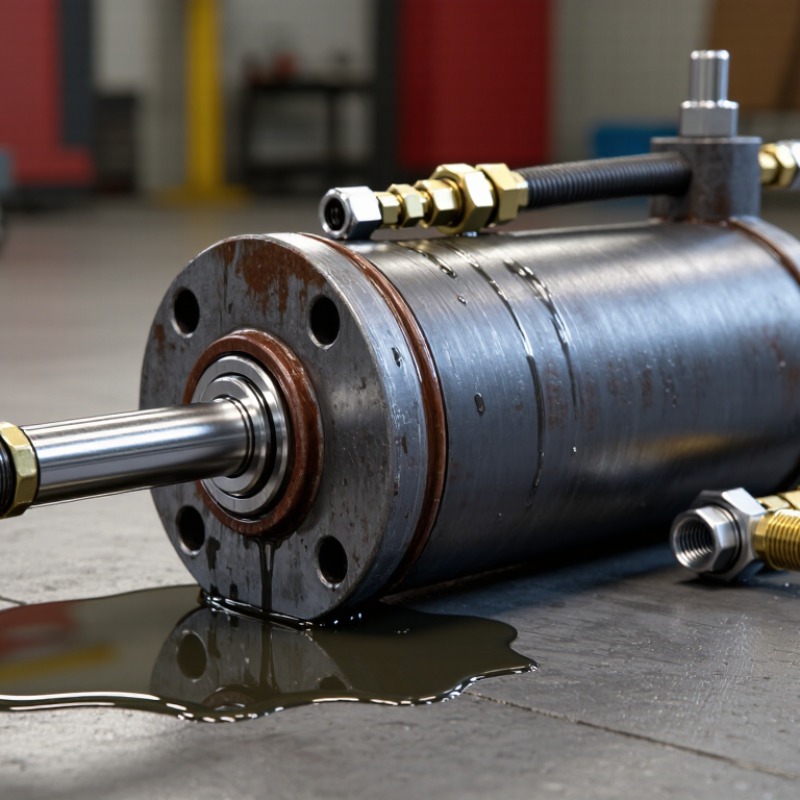
A leaking Hydraulic Oil Cylinder is more than a messy maintenance problem. It can signal worn seals, a damaged piston rod, loose fittings, excessive pressure, or contaminated oil. In real workshops, oil often appears beneath the cylinder before the actual failure becomes visible. A thin film around the rod may seem harmless, but it can quickly become a steady drip during operation.
Small leak. Big warning.
This guide explains how to identify common leak sources through practical inspection. Check the rod surface for scratches, dents, or rust marks. Examine seal areas for swelling, cracking, or hardened edges. Inspect ports and hoses for loose connections, damaged threads, or unusual vibration marks. Oil temperature and pressure also deserve attention, because heat can weaken seals while excessive pressure can force oil past them. Never rely on appearance alone. Clean the cylinder first, operate it carefully, and observe where fresh oil returns.
A trained hydraulic technician should confirm the diagnosis before parts are replaced. Manufacturer specifications, service records, and pressure-test results provide stronger evidence than guesswork. I have seen seals replaced when the real problem was a bent rod or misaligned mounting. That mistake wastes time and may cause another leak. Remote advice has limits, too. The exact cause depends on the cylinder design, working environment, oil condition, and operating history. Treat every leak as useful evidence, not an automatic reason to blame the seal.
Why Is My Hydraulic Oil Cylinder Leaking?
Classify External vs. Internal Leakage at 70–250 Bar Operating Pressure
At 70–250 bar, leakage classification should come before parts replacement. External leakage leaves oil outside the cylinder. Inspect the rod seal, gland, piston rod surface, port fittings, welds, and barrel joints. A clean rod may become wet after several cycles. Small droplets can then collect beneath the gland.
Do not touch a suspected pressure leak with your hand. Use cardboard or a suitable detection method after isolating pressure safely. Oil injected through skin is a medical emergency. I once dismissed a thin oil film as residue from maintenance. It returned during a warm-up cycle, which showed my first inspection was too casual.
Internal leakage stays inside the cylinder and often causes drifting or weak movement. A worn piston seal, scored barrel, damaged rod, or excessive clearance can let oil bypass the piston. With the load secured, record pressure and observe rod movement under a controlled test. Unwanted drift, rising oil temperature, or slow extension may indicate bypassing. Compare readings at low and high operating pressure. A cylinder can appear stable at 70 bar but drift noticeably near 250 bar. Check the control valve and hoses too, because they can imitate cylinder failure. Avoid replacing seals before confirming the fault. Surface damage may be the real cause.
| Leakage Classification | Where Oil Is Found | Typical Observable Symptoms | Common Causes | Behavior at 70–120 bar | Behavior at 120–180 bar | Behavior at 180–250 bar | Recommended Field Check | Typical Corrective Action | Priority |
|---|---|---|---|---|---|---|---|---|---|
| External leakage Rod-seal leakage |
Oil appears on the piston rod, wiper, or cylinder head and may run down the barrel. | Wet rod, oil ring near the head, visible drips during extension or retraction, increasing oil contamination. | Worn or damaged rod seal, scored rod, misalignment, excessive side load, hardened seal, contaminated oil. | May appear only during movement or near the end of the stroke. | Leak rate commonly increases as pressure, speed, temperature, and rod deflection increase. | Often becomes a continuous spray, stream, or rapid drip if the seal or rod is severely damaged. | Clean the rod, cycle the cylinder at low pressure, inspect the rod surface, check alignment, and look for a damaged wiper or seal. | Replace the rod-seal set; polish or replace a damaged rod; correct alignment and side loading; improve filtration if contamination is present. | High if oil reaches hot surfaces, creates a slip hazard, or rapidly reduces reservoir level. |
| External leakage Port, tube, or hose connection |
Oil is visible around fittings, adapters, hoses, tube ends, or manifold connections. | Fresh oil at a connection, a fine mist under pressure, audible hissing, or a pressure drop. | Loose connection, damaged O-ring, incorrect fitting, poor tube preparation, hose damage, vibration, thermal cycling. | A seep may be visible after several cycles; vibration can make the leak intermittent. | Seepage can become a spray or atomized mist, especially at small clearance points. | High risk of a pinhole jet or hose failure; the apparent leak point may be downstream from the actual defect. | Depressurize first. Clean the area, use cardboard to locate a jet, inspect fitting torque and O-rings, and never use a hand to search for leaks. | Replace damaged hoses, tubes, seals, or fittings; install correct components; support lines and retorque only when depressurized. | Critical for high-pressure jets, hose damage, or leakage near personnel or ignition sources. |
| External leakage Head, cap, or barrel seal |
Oil appears at the joint between the cylinder head, cap, and barrel. | Oil tracks around the end cap, leakage increases under load, or the barrel joint becomes visibly wet. | Damaged static seal, improper assembly, corrosion, warped mating surface, loose or overstressed tie rods. | Slow seepage may be present only when the corresponding chamber is pressurized. | Leakage generally becomes easier to reproduce during loaded operation. | Rapid leakage or a visible jet can occur if the static seal extrudes or the joint opens. | Clean and observe the joint while applying controlled pressure; check tie-rod condition and the correct seal orientation. | Disassemble safely, replace static seals, inspect mating surfaces, and tighten according to the cylinder manufacturer's procedure. | High because joint failure can release pressurized oil suddenly. |
| External leakage Cracked barrel, weld, or damaged body |
Oil emerges from a crack, weld seam, damaged barrel, or mounting area. | Localized wet spot, growing crack, sudden pressure loss, or oil released only under load. | Impact damage, corrosion, excessive pressure, fatigue, incorrect mounting, or side loading. | A crack may remain difficult to see until the cylinder is loaded. | Leakage can open and close with load direction or cylinder position. | Very high risk of rapid structural failure and uncontrolled actuator movement. | Isolate the equipment, release stored energy, clean and visually inspect; use dye penetrant or other approved non-destructive testing where appropriate. | Remove from service and replace or professionally repair the cylinder; investigate overload, mounting, and pressure-control problems. | Immediate shutdown |
| Internal leakage Piston seal bypass |
No external oil may be visible; oil passes from the high-pressure side to the low-pressure side inside the cylinder. | Load drift, failure to hold position, reduced force, slow movement, or heat generation without an external leak. | Worn piston seal, damaged seal groove, scored or corroded bore, excessive clearance, contaminated oil, thermal degradation. | Drift may be slow and noticeable mainly when holding a suspended or resisting load. | Bypass becomes more apparent as differential pressure and oil temperature rise. | Rapid drift, poor load holding, and substantial heat may occur; component damage can accelerate. | Isolate the directional valve, cap the cylinder ports with rated test equipment, monitor position drift, and compare pressure decay on each chamber. | Rebuild or replace piston seals; inspect bore, piston, and grooves; flush contaminated oil and correct filtration or alignment issues. | High where unexpected movement can injure personnel or damage equipment. |
| Internal leakage Directional valve or counterbalance valve |
Oil leaks internally through the control valve rather than from the cylinder body. | Cylinder drift continues even when the cylinder itself passes a pressure-holding test; valve may be warm or noisy. | Spool clearance, worn poppet or seat, contamination, damaged cartridge seal, incorrect pilot pressure. | Small internal flow may cause gradual drift or delayed response. | Drift and temperature rise become more noticeable under sustained load. | High differential pressure can increase bypass flow and make load control unstable. | Block or isolate the cylinder ports, then test the valve separately with calibrated gauges and the correct schematic. | Clean or replace the valve element, renew cartridge seals, verify pilot pressure, and correct contamination sources. | Medium to high, depending on load-holding requirements. |
| Internal leakage Cross-port or circuit bypass |
Oil moves through a relief valve, check valve, hose connection inside a manifold, or another circuit path. | Unexpected movement, pressure decay, heating, or drift that changes when other functions operate. | Relief valve set too low, leaking check valve, incorrect plumbing, manifold contamination, or failed load-control component. | System may function but fail to maintain pressure during a static hold. | Relief or bypass flow can produce measurable heat and slower actuator speed. | Persistent high-pressure bypass may overheat oil and cause repeated relief-valve operation. | Review the hydraulic schematic, isolate branches, compare pressure at both cylinder ports, and check relief-valve operation with calibrated instruments. | Correct plumbing, service the leaking valve, reset only to the approved system pressure, and replace contaminated components. | Medium to high, with immediate action if overheating or uncontrolled motion occurs. |