How to Choose the Right Hydraulic Cylinder Shaft?
Choosing the right Hydraulic Cylinder Shaft requires more than matching diameter and stroke. Surface finish, material strength, buckling resistance, and side loading affect service life.
Grand View Research estimates the global hydraulic cylinders market reached approximately USD 14.7 billion in 2023. The report expects continued growth through 2030, driven by construction, agriculture, and industrial equipment. That figure is an estimate, not a purchase specification. Still, it shows the scale of decisions surrounding cylinder components.
Anthony Esposito, author of Fluid Power with Applications, explains, “The cylinder converts fluid power into mechanical power.” His point remains practical: the shaft must transfer force reliably under changing loads. A polished 50-millimeter shaft may perform well in a clean factory. The same shaft can suffer quickly in abrasive mining dust. Chrome thickness, rod straightness, seal compatibility, and mounting alignment all matter. ISO 6020/2 and ISO 6022 provide useful dimensional and performance references, but standards cannot replace application testing.
There is no universal best shaft.
This guide examines how to choose a Hydraulic Cylinder Shaft for pressure, stroke, load, environment, and maintenance demands. Engineers should calculate compression loads before selecting a larger diameter. They should also inspect corrosion risks, coating damage, and unsupported length. A perfect calculation rarely survives every real-world condition. Field experience may reveal unexpected vibration, uneven mounting, or contamination. That is why reliable selection combines manufacturer data, recognized standards, and honest review of operating evidence.
Understanding the Role of a Hydraulic Cylinder Shaft
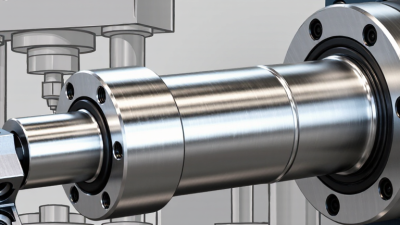
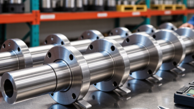
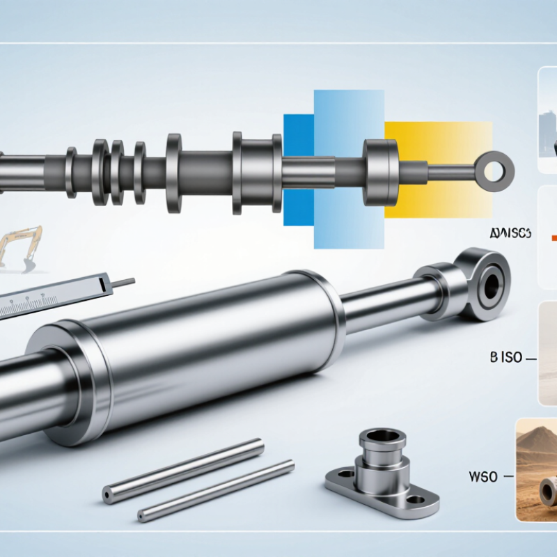
A hydraulic cylinder shaft, often called a piston rod, transfers hydraulic pressure into mechanical movement. It pushes, pulls, and guides the piston through each working cycle. Its surface also supports the rod seal, so small scratches can cause leaks. That role makes shaft selection more important than appearance alone.
In field inspections, I check the load direction, stroke length, mounting alignment, and operating environment. A slender shaft may bend under a side load, even when its rated force looks adequate. A longer stroke can increase buckling risk. Corrosive moisture may damage exposed surfaces. Hard chrome plating, stainless steel, or another suitable finish can improve resistance, but the choice depends on temperature and fluid conditions. A perfect calculation is helpful. It is not the whole inspection.
Tips:
Match shaft diameter to load and stroke, not pressure alone. Check surface finish near the seal. Measure alignment during installation. Leave room for thermal movement. I also recommend reviewing unusual vibration after the first operating hours. This step is easy to skip. That can be a costly mistake. Record wear patterns, seal condition, and visible bending during maintenance. These details often reveal problems before the shaft fails.
Identifying the Required Load, Stroke, and Operating Conditions
Choosing a hydraulic cylinder shaft starts with the real load, not the catalog size. Calculate force from pressure and piston area, then include friction, shock, and side loading. A practical design often uses a 1.25 to 1.5 service factor, depending on duty severity. A neat calculation can still be wrong. Field measurements may reveal uneven loading.
Define the required stroke with the machine fully retracted and extended. Add clearance for attachments, alignment, and mechanical stops. Then check rod buckling, especially when the cylinder pushes through a long stroke. ISO 4413 recommends controlling hydraulic-system risks through proper sizing, installation, and verification. Cylinder speed also matters: flow rate determines movement time, while frequent cycling increases heat and seal wear. Keep the calculation visible.
Operating conditions can change the shaft specification. Outdoor equipment may face water, dust, freezing temperatures, and impact. Indoor systems may face high temperatures, abrasive particles, or continuous duty. Specify the mounting style, rod-end connection, surface protection, allowable side load, and maintenance access. According to Grand View Research’s 2024 hydraulic-cylinder market assessment, global demand is expected to grow steadily through 2030, driven partly by construction and industrial automation. That growth does not make selection easier. Test the cylinder under the worst realistic load, not only the average load. And reconsider the design if the shaft bends, vibrates, or runs hot during testing.
How to Choose the Right Hydraulic Cylinder Shaft? - Identifying the Required Load, Stroke, and Operating Conditions
| Application Profile |
Required Load
(kN) |
Recommended Stroke
(mm) |
Typical Working Pressure
(bar) |
Suggested Bore Diameter
(mm) |
Suggested Shaft/Rod Diameter
(mm) |
Estimated Extension Force
(kN) |
Recommended Buckling Safety Factor |
Operating Conditions |
| Light-duty lifting mechanism |
8–12 |
150–300 |
100–160 |
40–50 |
20–25 |
12.6–31.4 |
2.0–2.5 |
Indoor or sheltered use; moderate cycle frequency; clean hydraulic fluid. |
| Material handling equipment |
25–40 |
300–600 |
160–210 |
63–80 |
32–45 |
49.9–105.6 |
2.5–3.0 |
Frequent starts and stops; side loads should be minimized; guided mounting is preferred. |
| Agricultural implement |
35–60 |
400–800 |
180–210 |
80–100 |
45–56 |
90.5–164.9 |
3.0–3.5 |
Outdoor exposure, dust, mud, vibration, and variable loads; use protected wipers and corrosion-resistant finishes. |
| Construction equipment |
70–120 |
500–1,000 |
210–350 |
100–125 |
56–70 |
164.9–429.5 |
3.0–4.0 |
High shock loads, contaminated environments, and uneven terrain; use robust mounts and load-holding protection where required. |
| Industrial press or compactor |
100–180 |
200–500 |
250–350 |
100–140 |
63–90 |
196.3–539.8 |
2.5–3.0 |
High force with controlled motion; verify pressure spikes, duty cycle, heat generation, and end-of-stroke cushioning. |
| Long-stroke positioning system |
20–50 |
1,000–2,000 |
100–210 |
63–100 |
40–63 |
49.9–164.9 |
4.0 or higher |
Long unsupported extension increases buckling risk; use external guidance, reduced side loading, and suitable cushioning. |
Selection reference: Extension force is estimated from piston area and working pressure using
F = P × A. Actual cylinder sizing must also account for retraction force, dynamic impact, mounting alignment, side loading, pressure spikes, temperature, cycle frequency, and the required service life.
Selecting the Shaft Material, Diameter, and Surface Finish
Choosing a hydraulic cylinder shaft requires more than matching the bore size. Material selection affects strength, corrosion resistance, and fatigue life. Medium-carbon alloy steel is common for demanding cylinders because heat treatment improves tensile strength and toughness. In corrosive environments, stainless steel can reduce maintenance, but its lower hardness may increase scratching risk. ISO 6020/2 covers cylinders designed for working pressures up to 160 bar, while ISO 6022 addresses heavy-duty designs up to 250 bar. These limits should guide the initial material and wall-thickness review.
Diameter must resist buckling, bending, and side loading. Engineers often use Euler buckling calculations, then apply a safety factor based on mounting conditions and stroke length. A long, slender shaft can fail even when system pressure stays within limits. For example, a 50 mm shaft with a 1,500 mm unsupported stroke needs more careful checking than a shorter shaft carrying the same load. ISO 4413 emphasizes risk control and safe hydraulic design, but field alignment is still frequently underestimated. That is a practical weakness.
Surface finish directly influences seal wear and leakage. Many rod designs target roughly 0.2–0.4 μm Ra after grinding and polishing, although the seal supplier’s limits should control. Excessive roughness cuts sealing lips; an overly smooth surface may retain too little lubricant. Industry maintenance reports repeatedly identify contamination as a major cause of hydraulic failure, so chrome, nickel, or ceramic-style coatings should be selected according to the fluid, environment, and cleaning schedule. Measure the finished shaft, not only the drawing.
Checking Compatibility with Seals, Mounts, and Hydraulic Components
Choosing the right hydraulic cylinder shaft starts with the parts around it, not the shaft alone. The rod must match the seal profile, gland design, mounting arrangement, and hydraulic circuit. A polished surface may look ideal, yet the wrong diameter can cut a seal during installation. Measure carefully. Confirm rod diameter, length, thread form, shoulder position, and allowable side load. Even a small mismatch can create leakage, scoring, or uneven cylinder movement.
Seal compatibility deserves close attention. Check the fluid type, operating temperature, pressure, and seal compound recommended for the cylinder. Mineral oil, water-based fluid, and biodegradable fluid may require different sealing materials. Also inspect the wiper seal. A damaged wiper can carry dust into the gland and wear the shaft quickly. Do not rely on appearance alone. During maintenance checks, compare the old shaft’s wear pattern with the seal condition. That comparison often reveals misalignment rather than poor material. Still, the diagnosis is not always clean.
Mounts and hydraulic components must work as one system. Verify clevis width, pin diameter, spherical bearings, and the cylinder’s mounting centerline. The shaft should extend without bending, binding, or forcing the mount sideways. Check port size and flow requirements too. Restricted flow can make a suitable shaft seem faulty. Before ordering, compare drawings, tolerances, and actual measurements from the machine. Catalog dimensions are not enough when a frame has wear. Rechecking alignment takes time, but replacing a scored shaft takes more.
How to Choose the Right Hydraulic Cylinder Shaft?
Checking compatibility with seals, mounts, and hydraulic components starts with the shaft surface finish. The chart shows typical maximum shaft roughness targets for common dynamic seal materials. Lower Ra values generally reduce seal wear and leakage risk.
Seal compatibility
Use a hardened, corrosion-resistant rod with a polished sealing track. Confirm the seal material, pressure, speed, temperature, and fluid compatibility.
Mount compatibility
Match the rod diameter and end connection to the rod eye, clevis, spherical bearing, guide, and available misalignment.
Hydraulic component fit
Check the shaft load, stroke, buckling risk, side loading, hydraulic pressure, and connection size before final selection.
Values are typical engineering targets in micrometres Ra and can vary by seal profile, manufacturer specification, pressure, speed, lubrication, and surface treatment. Always verify the final limits with the seal and cylinder design requirements.
 +86-13349293098
 Contact WhatsApp
 Contact Email